Roboconf's Eclipse plug-in
This page lists the modeling Eclipse features for Roboconf.
Creating a New Diagram Project
Click File > New > Project.
Then select Roboconf > Diagram Project for Roboconf Graphs.
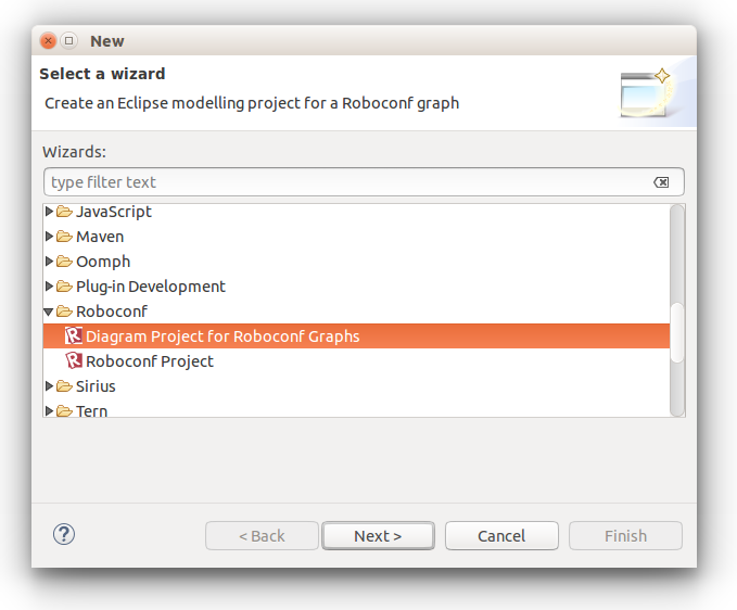
Click Next.
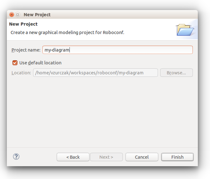
Give your project a name and click Finish. On wizard completion, a project is created and an editor is visible. For those who are familiar with Eclipse, this project is now compliant with Sirius.
The Sirius Modeler
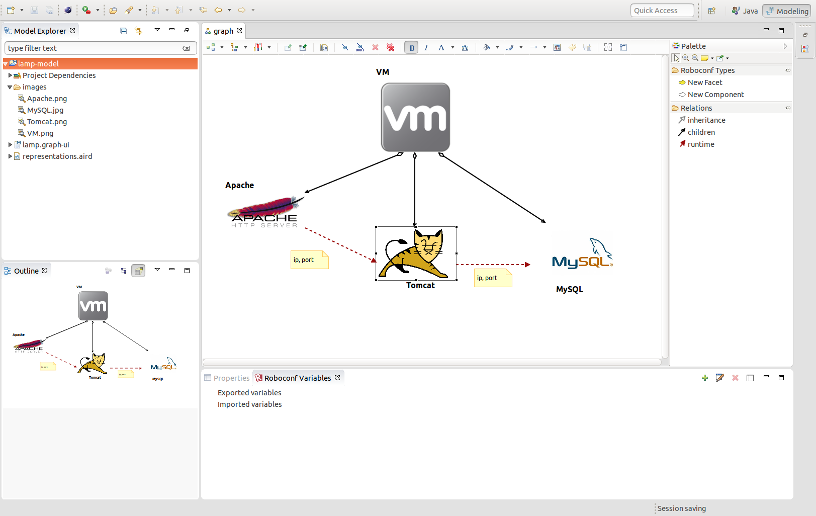
You can use the palette on the right to add new Roboconf facets and components on the drawing area. You can also define the relations between the graph elements: inheritance, containment (children) links and runtime relations.
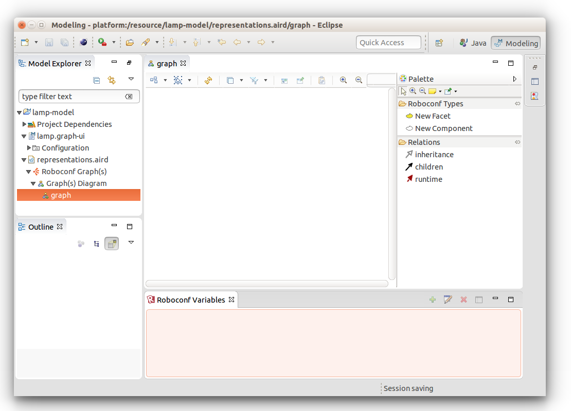
Here is a summary of the available operations.
- Clicking a node label allows you to edit its name.
- Double-clicking a node allows you to select an image on your disk.
This image will be imported in the project under images and used in the diagram. - Double-clicking a runtime link allows to edit imported variables.
- Right-clicking the diagram shows a menu to export it as an image.
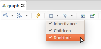
You can also use the layers icon (at the top) to filter the relations you want to see.
It does not delete the links (the model remains the same). Only the representation is impacted.
You can also manage exported and imported variables by using the Roboconf variables view.
To open it, click Window > Show View > Other and select Roboconf > Roboconf Variables.
Code Generation
This modeler allows you to build visual representations of Roboconf graphs.
From these representations, it is also possible to generate a graph file or even a Roboconf project.
Once your diagram is complete, right-click the graph-ui model file in the explorer and select
Roboconf > Generate Files.
A wizard shows up and provides various options to generate artifacts.
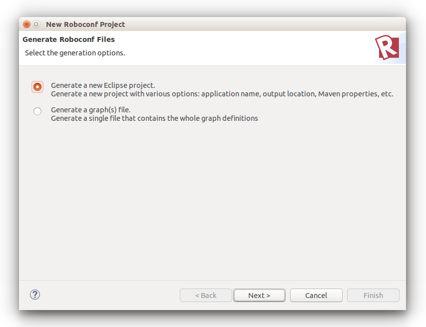
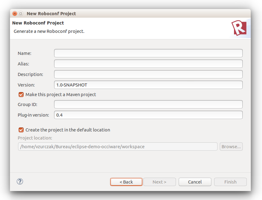
The project generation page is very similar to the one to create a new Roboconf project.
The main difference is that the graph will be exactly what you modeled graphically.
Creating new Representations (Advanced)
As for any Sirius modeler, representations are stored in the representations.aird file.
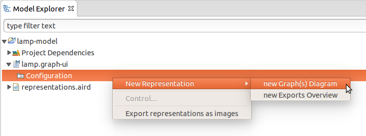
In the Model Explorer, find the configuration element under the graph-ui file.
Right-click it and select New Representation > New Graph(s) Diagram.
Give a name to your representation (e.g. graph) and click OK.
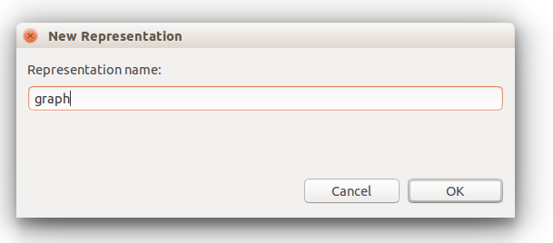
The representation is now visible in a Sirius modeler.